Ok so I found out about the weird and quirky Boss RSD-10 a while back and finally had one pop up in my eBay notifications. Once I got the unit in I wanted to immediately do the “wet mod” that I had read about on the Muff Wiggler forums and Youtube. Unfortunately the extent of the instructions on how to do the mod were essentially “open it up and pull out the C4 capacitor” 🤔 Fortunately I’m fairly familiar with doing mods and repairs like the Yamaha SU700 encoder fix I posted about a few years ago.
So… my gamble is your gain. The following is a step-by-step guide (for the most part) on how to remove the C4 capacitor from your Boss RSD-10 sample delay unit. All you need is a soldering gun, a solder-sucker, some solder, a pair of pliers, and a screwdriver or two.
Here’s an all-in-one soldering kit if you don’t have any of them.
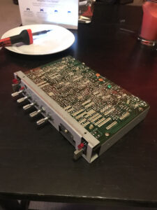
Here’s the RSD-10 in all it’s glory, ready for surgery: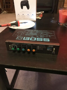
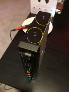
First, undo the side screws on the left and right side of the unit. There’s four of them.
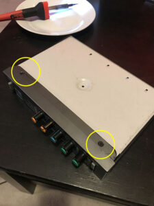
Next, remove the two bottom screws.
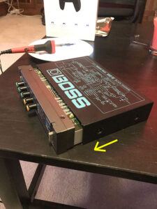
Then, slide the back of the casing off the unit. Be firm but gentile. It’ll come off.
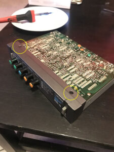
Now remove the two screws on the top of the face plate.
You should now be able to remove the plastic face plate.
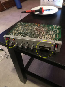
Now remove the protective plastic sheet cover screw and the pan-pot nuts. This will let you remove the front metal casing. When you get them all off, gently remove the metal casing. Be careful of the left-most pan pot as it’s not PCB mounted and sort of ‘free floating’.
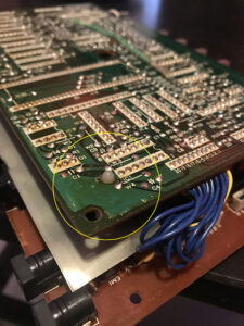
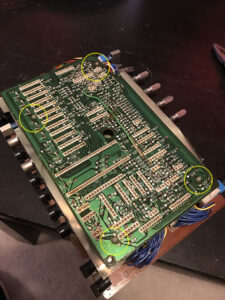
You’ll need to de-solder the four grounds on the back of the unit. Just heat up the solder on each lead the ground wires are attached to (there’s four total) and use your solder-sucker to remove the solder. Then pull the ground wire away from the PCB. One ground wire has two capacitors(?) attached to the same lead, so make sure to not move them too much and re-solder everything similarly together at the end.
Remove the four PCB screws so you can separate the two PCB boards. There’s two regular ones, and two that look like they have grounds underneath them. You’ll see what I mean when you undo them.
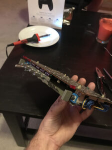
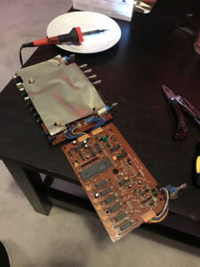
Now use your pliers to pinch the little plastic nipples extruding from the PCB. These have little plastic tabs you need to depress in order to get the top PCB off the bottom PCB. Do each one at a time and eventually the top PCB will be loose. You should then be able to flip it over on it’s side. Make sure to flip it on the side with the ribbon cable.
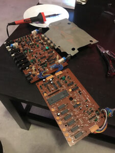
Now remove the plastic protective liner from the bottom PCB and set aside.
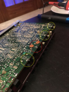
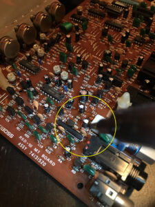
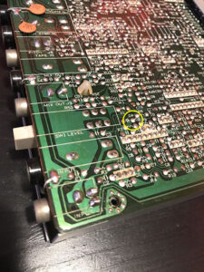
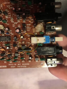
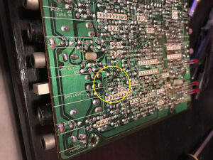
Now locate the C4 capacitor. Figuring out which solder points to de-solder can be confusing, so use the photos below to reference which ones to undo so you can pull the C4 capacitor out.
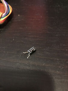
Once you’ve located the C4 capacitor, heat up the leads and remove the solder with the solder-sucker. Then, use your pliers to carefully pull the C4 capacitor out. Your PCB should look like this afterwords:
Now that you’ve got it out, reverse these directions (leaving the C4 capacitor out) and solder everything back together. If you do it all in order it should be a fairly easy process.
Now power the RSD-10 up and test out by sending some signal into it. If you’ve done everything properly you should have 100% wet signal, and the ‘effect’ knob will just raise or lower the volume of the unit instead of blend the wet into the dry. There should be no more dry signal at all.
Make sure to save the C4 capacitor in case you ever decide you’d like to put it back to stock. This delay box is so weird I can’t ever see that happening for me, but I like to save things anyways just in case.
Feel free to message me if you have any questions and let me know if this was helpful!
@scottbrio on Twitter, Instagram, Facebook, and everything else 🙂
Julianna Deluxe Review - Walrus Audio // Pedals + Synths, & Samplers
Ok so I found out about the weird and quirky Boss RSD-10 a while back and finally had one pop up in my eBay notifications. Once I got the unit in I wanted to immediately do the “wet mod” that I had read about on the Muff Wiggler forums and ...
| Play | Cover | Release Label |
Track Title Track Authors |
|---|


